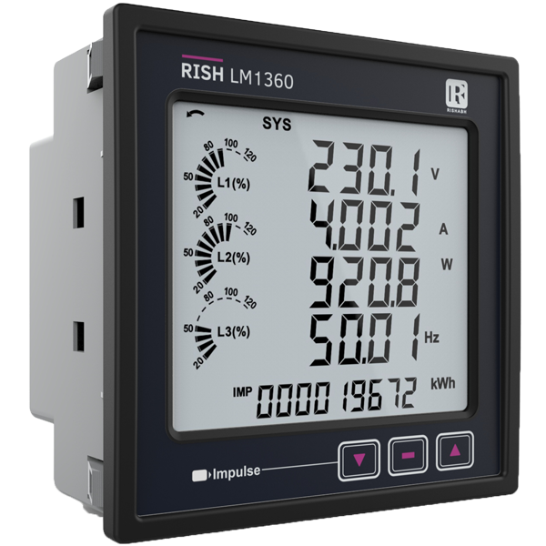
Overview
Active Energy – Class0.2S as per IEC 62053-22
Energy measurement
Active energy Import (kWh),Active energy export (kWh) Reactive energy Inductive(kVArh),Reactive energy capacitive(kVArh), & Apparent energy (kVAh). Any of the parameters can be freely assigned to 2 optional pulse outputs.
Auto Energy Ranging Count on Display
The Energy count rollover from WATT to KWATT then to MWATT has energy increases over the period.
Programmable Energy format & Energy rollover count
Customer can assign the format for energy display on MODBUS (RS485) in terms of W, kW or MW. Additional to this, customer can also set a rollover count from 7 to 9 digits, after which the energy will roll back to zero. The above settings are applicable for all types of energy.
Total Harmonic Distortion (THD)
The instrument can measures per phase THD of voltage & current, and it also measure individual 31st harmonic of voltage and current(Display on Modbus only).
Wide Auxiliary Supply
It can accept Input from 100 VAC/DC to 550 VAC/DC
Wide Input Voltage Measurement
Measurement wide range of input voltage 100VLL to 600VLL.
User selectable CT Secondary 5A/1A
The secondary of external Current Transformer (CT) can be programmed on site to either 5A or 1A locally via front panel keys by entering into Programming mode or remotely via MODBUS (RS485)
On site programmable PT/CT ratios
It is possible to program primary of external potential Transformer (PT), primary of external Current Transformer (CT) on site locally via front panel keys by entering into Programming mode or remotely via MODBUS (RS485).
User selectable PT Secondary
The secondary of external potential Transformer (PT) can be programmed on locally via front panel keys by entering into Programming mode or remotely via MODBUS (RS485).
User selectable 3 phase 3W or 4W
User can program on site the network connection as either 3 Phase 3 Wire or 4 Wire locally via front panel keys by entering into Programming mode or remotely via MODBUS (RS485).
Onsite selection of Auto scroll / Fixed Screen
User can set the display in auto scrolling mode or fixed screen mode locally via front panel keys by entering into Programming mode or remotely via MODBUS (RS485).
Parameter Screen recall
In case of power failure, the instrument memorizes the last displayed screen.
Phase reversal indication
The instrument can detect wrong phase sequence or failure of one of the input voltages and displays “phase” error message.
User selectable Low Current suppression (below 30 mA)
User can suppress the readings below 30 mA in the current measurement by onsite programming if required.
Min Max storage of parameters possible
The instrument stores minimum and maximum values for System Voltage and System Current.
Run Hour, ON Hour, Number of Interruptions
Run Hour records the number of hours load is connected. ON Hour is the period for which the auxiliary supply is ON. Number of Interruptions indicates the number of times the Auxiliary Supply was interrupted.
Optional MODBUS (RS485) Output
The optional ModBus output enables the instrument to transmit all the measured parameters over standard MODBUS (RS485).
User Assignable Registers for MODBUS
Customer can assign MODBUS register address as per his need for faster response time.
Optional 2 Relay Output ( Pulse output / Limit switch)
The instrument can be programmed as Pulse output or Limit Switch.
Pulse Output: The optional pulse output is a potential free, very fast acting relay contact which can be used to drive an external mechanical counter for energy measurement.
Limit switch: The instrument will trip the one or two relays if the programmed parameter exceeds the programmed High & Low Limits.
Configuration of the Instrument via MODBUS
The instrument settings can be configured locally via front panel keys by entering into Programming mode or remotely via MODBUS (RS485).
Optional Analog Outputs ( 2 Outputs)
2 Analog outputs can be programmed from a list of input parameters.
Ethernet Interface (Modbus TCP/IP Protocol)
The optional Ethernet Interface output transmit all the measured parameters on Modbus TCP/IP. Also user can configure their instrument via Ethernet Interface.
Enclosure Protection for dust and water
Conforms to IP 54 (front face) as per IEC60529.
Compliance to International Safety standards
Compliance to International Safety standard IEC 61010-1- 2010.
EMC Compatibility
Compliance to International standard IEC 61326.